Cranes, hoists and elevators
Lifting and lowering loads is a key application of AC drives, so it's worth examining these key users of inverters in more detail.
When you lift something, you are clearly doing work; If you lower a bit when you're not using a brake (or too much friction) then you're taking energy from the load so there's regeneration. This means that in most applications we have to decide what to do with the energy coming back from the motor. The Braking and Regeneration article explains this. In practice, this means choosing a suitable braking resistor based on the size of the frequency converter, the duty cycle, etc. Since most elevators are counterbalanced, they don't necessarily motor and generate when you expect them to; Lifting an empty car will likely result in regeneration.
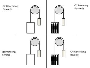
Elevators go up and down, full and empty. This means that the drive must run forwards and backwards, motorize or regenerate. This is called a four quadrant operation. However, cranes will be fairly close to regeneration, lowering a hook or load and traveling while lifting, and therefore only operate in two quadrants. The four-quadrant operation of an elevator is shown in Figure 1.
Fig. 1: Four-quadrant operation in an elevator
Regenerative braking controls the speed of the elevator or crane, but a separate electromechanical brake is required to completely stop the movement. These are often controlled by the frequency converter via one of its output relays. Brake release is normally delayed to allow magnetizing current and torque to build up in the motor. This ensures that when the brake is released, the load does not drop while the motor increases torque. The brake is also applied shortly before the engine comes to a standstill. Parameters allow these times to be adjusted. On some drives like the Invertek P2, the motor torque is measured and must reach a certain preset adjustable level before the brake is released. This is called torque testing.
Remember if the relay is used to control an electromagnetic brake a separate contactor (controlled by the relay) must be used as the brake is very inductive and easily damages the relay.
As can be seen from the above, controlling the motor when releasing the brake can be difficult. Until the motor senses the load and starts spinning, it is not clear if the load is regenerating or motoring. The elevator can be full (tends to fall) or empty (tends to rise due to the counterweight). If the elevator falls down even a little bit before going up, it's not really acceptable to the passengers in the car. An encoder is often used to reduce this effect.
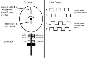
An encoder is a small sensor mounted on the back of the motor and connected to the rotating shaft. As the shaft rotates, a disk mounted in the encoder rotates, and slots in the disk interrupt the light from an LED on one side of the disk and shines onto a photo sensor on the other side. A series of pulses is thus generated, the frequency of which is proportional to the engine speed. If there are two sets of slots and photo sensors, the direction of rotation can be determined if the slots are offset. The number of slots varies; 1024 per revolution is typical. Figure 2 shows how the encoder works.
Fig. 2: Encoder operation
When the encoder output is connected to the drive - and the drive has the appropriate inputs to read and interpret the encoder signal - the drive can detect the slightest movement when the brake is released and respond accordingly. Further monitoring of the signal can be used to allow precise speed control.
Until recently, encoders were pretty much standard equipment in elevators and cranes for this reason. However, recent improvements in vector control have made it possible to achieve similar levels of performance as encoder control systems using vector control alone.
Once stopping and starting is figured out, raising and lowering is pretty easy. There may be some safety issues, and larger cranes may have features such as anti-swing software and truss and travel systems. These together make a complex machine and can also use fully regenerative drives with high power.
Elevators are a bit more difficult. They must produce a smooth, confident ride and stop within a few millimeters of the ground. There are also safety issues and emergency operations that need to be considered.
These functions can be achieved with a standard drive, but many manufacturers, including Invertek, produce a specific drive for elevators, with software and hardware to meet these requirements.
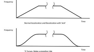
For example, to avoid vehicle judder during acceleration and deceleration, S-curves are used to ensure smooth stopping and starting. An optional encoder interface module can be mounted on an encoder if required. Modern elevators use large multi-pole permanent magnet gearless motors so the drive is designed to work with these. Figure 3 shows these S-curves.
Fig. 3: S-curves
Other features may include control of an output contactor and rollback compensation to improve ground alignment when using an encoder.
An important requirement of any elevator system is emergency operation. If the power goes out, the elevator should be able to move to the next floor to allow evacuation. This can be achieved, for example, with a 24V battery that slowly powers the drive. The drive requires significant hardware modifications to do this. Another solution is to install an inexpensive uninterruptible power supply (UPS) that can supply the drive with 230V for a short time. With minor design changes, a 400V drive can be powered from the UPS in emergency mode. Either way, the car can slowly move to the next floor, and the passengers can exit into the dark corridor.
The software that controls elevator traffic is highly complex. Consider a six-elevator system with calls from many floors, up and down, priority requests, etc. Fortunately, this is the job of the elevator supplier, not the drive engineer.


