Features
- Brakesystem according to DIN EN 19085-1, Pl = b according to DIN EN ISO 13849-1
- High operating reliability
- High withstand voltage
- Maintenance free
Option
- Continuously adjustable braking current
Models and Prices KLIBO-Phase-Brake
| Image | Description | Art.-No. | Price incl. VAT |
|---|---|---|---|
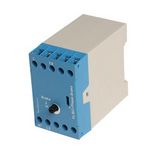
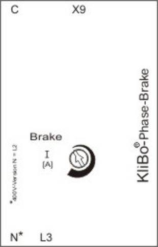
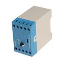 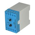 | 230 V~ | 8503.4562 (previously 8503.4554) | € 77,80 Get a quote In Stock: 0 |
| 400 V~ | 8503.4558 | € 81,31 Order In Stock: 16 | |
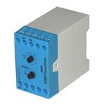
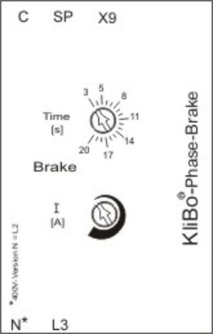
| 230 V~ with SP-contact and adjustable active braking time | 8503.4555 | € 81,46 Order In Stock: 49 | |
| 400 V~ with SP-contact and adjustable active braking time | 8503.4559 | € 83,45 Order In Stock: 155 |
Functional description
The KLIBO Phase Brake Module is designed for the braking of squirrel-cage and single-phase motors with starting capacitor. The integrated power electronics generate a direct current that causes a stationary magnetic field in the motor winding and slows down the rotor. The magnetic field strength and thus the braking force is determined by the height of the continuously adjustable direct current. The module allows stepless adjustment of the braking current as well as the active braking time, which can be controlled via the SP input (optional). The KLIBO phase brake module is connected directly to the motor winding via power contactors, which are controlled by the KLIBO Star Delta module.
Motor heating during brake operation
The motor heating during DC injection braking corresponds to the heating at engine start. If motors are frequently started and braked with high currents, the motor temperature should also be monitored by a thermistor (temperature sensor).
We have profound experiences in braking moduls for many years. That's why we are the right partner for electronic brakes.
Technical data
| Rated voltage ranges | 110 V~, 230 V~, 400 V~ |
| Perfomormance level | PL = b according to DIN EN ISO 13849-1 |
| PFH | 4.23x101h6 |
| Certification number | IFA1603009 |
| Rated frequency | 50-60 Hz |
| Voltage range | 85-110 % |
| Rated capacity | 2 VA |
| -20° C ... +50° C |
| Optional, same potential as input L3 |
| 3 s ... 30 s |
| 0-20 A |
| Thyristor = 30 A/1200 V Diode = 40 A/1200 V |
| Approx. 250 ms |
| 10 % ED at 10 s braking time (36/h) |
| Function |
|
|
|
| Use | Sinusoidal mains voltage necessary. No generator operation |
| Housing 10 poles | Top hat rail housing |
| Mounting |
|
| Housing dimensions | 45.5 mm x 74 mm x 85 mm (LxWxH) |
| Max. terminal cross-section | 2.5 mm² |


