


Thermal overload protection relay BR63 for contactors Iskra KNL43...KNL75
According to IEC/EN 60947-4-1

Features
- 3 pole overload relay
- Protection for motors up to 47 A operating current and 690 V operating voltage
- Electrically isolated auxiliary contacts (1 NO, 1 NC)
- Manual or automatic reset selectable
- Phase failure sensitivity according to IEC/EN 60947-4-1
- Temperature compensation
- UL approval
- Degree of protection IP20
Versions and prices Thermal overload relay ISKRA BR63
| Image | Setting range (A) | Factory number | Max. backup fuse gL/gG (A) | Power loss | Art.-No. | Price incl. VAT |
|---|---|---|---|---|---|---|
| 17 - 25 A | 786.050.504 | 100 | 11...15,5W | 4036.7371 | € 37,81 Order In Stock: 14 |
| 24.5 - 36 A | 786.050.505 | 100 | 4036.7372 | € 37,81 Order In Stock: 11 | ||
| 35 - 47 A | 786.050.506 | 125 | 4036.7373 | € 37,81 Order In Stock: 2 |
Functional description
This thermal overload relay indirectly monitors the temperature of the motor winding via the current flowing in the supply line. A separate bimetal with associated heating coil is provided for each current-carrying line to the motor. If the current drawn by the motor exceeds the specified value for a certain period of time, the bimetal, which has been deformed by heat, releases contact 95-96 and thus interrupts the control circuit to the motor. An additional mechanical construction means faster tripping if a phase fails. With the correct dimensioning and setting, the motor is therefore well protected against overload, non-starting and phase failure.
Technical data
| Designation | BR63 |
| Rated operating voltage Ue | 690 V |
| Impulse voltage withstand Uimp | 6 kV |
| Allowed ambient temperature | -5 °C ... +55 °C = Operating temperature |
| Mounting position | Any |
| Mounting | Hoot at the contactor, screw at the main terminal |
| Connecting terminals | Screw terminals |
| Operating temperature | 2x 6,0 - 35 sq.mm (finely stranded with AEH) 2x 0,75-2,5 sq.mm (finely stranded with AEH- auxiliary contacts) |
| Adjustment range | See model and article number |
| Tripping class | 10 |
| Frequency of operation | Up to 15 shifts / h or 60 shifts / h with 40 % |
| More technical data | Data sheet |
| Tripping characteristic | Characteristic curve |
| Technical drawing | Dimensions |
Settings and notice
Warning:
Insufficient tightened terminal screws result in excess warming. The device may only be mounted by professionals. Don't touch parts under voltage.
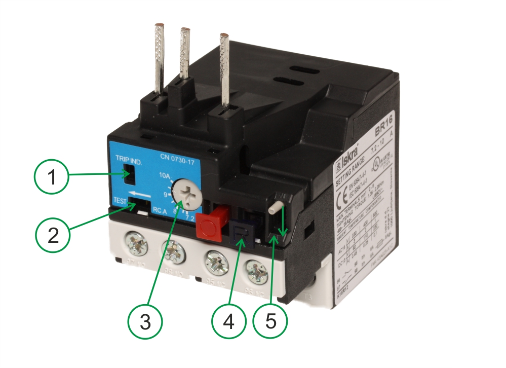
Check start of operation:
Press cutout switch "O" to reset the relay. Pressing the slide "2" in direction of arrow triggers the device. Contact 95-96 opens, contact 97-98 closes. In switch off mode the position indication device "1" shows yellow.
Adjust motor rated current:
To adjust the rated motor current turn the control knob "3" to the desired value.
Changeover manual - automatic reset:
Manual reset:
The button "4" resets the triggered overload protection. Please ensure adequate cooling time.
Automatic reset:
Press button "R"(4) and hold it. At the same time move slide (5) in direction of the arrow until it is latching. After letting go the slide the button "R"(4) must stay in it spressed in position
Auxiliary switch:
NC 95-96, NO 97-98, electrically isolated. Short-circuit protection of the auxiliary switches 6 A gl. Auxiliary contakt 97-98 can trip an indicating circuit. Bridging connection 95 and 97 realizes an changeover contact.